The practical answer.
Review the battery, charger, dock contacts, firmware and recovery behavior as a single integration task.
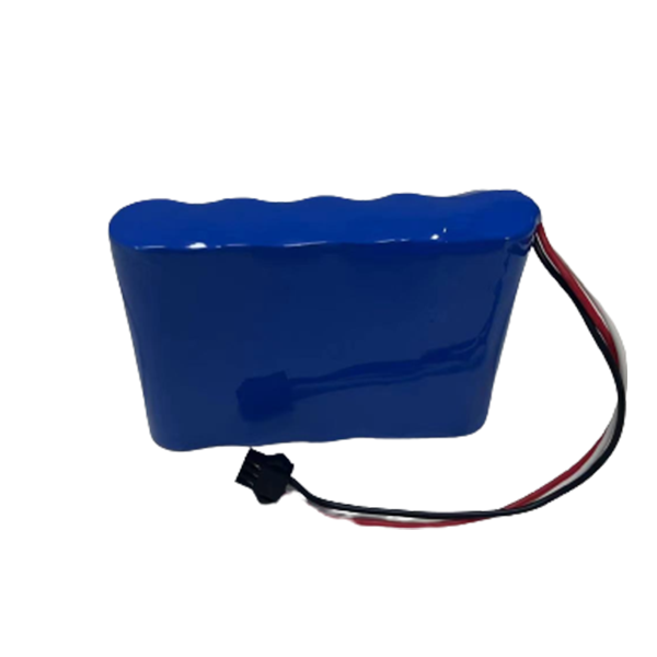
Define the complete charging path
A charging dock connects several systems: the robot's battery, its internal electronics, external contacts and the charger. Start with a diagram showing that path and identify which device controls charging. Record the intended charging current and voltage using the approved battery specification. Describe alignment, contact engagement and the sequence for enabling power. A battery specification alone cannot establish that the assembled dock works reliably. The product team should review the physical and electrical interface together before freezing the robot's mechanical design.
Plan the normal operating sequence
Write down how the robot approaches, connects, confirms charging, completes charging and leaves the dock. Specify what information is exchanged and which checks must pass at each stage. Include the equipment state while docked, because onboard computers and auxiliaries can consume part of the supplied power. Ask how this affects the expected time to become ready for another mission. A theoretical charge-time estimate may be misleading if it ignores the load that continues running during charging.
Review interruptions and recovery
Consider an interrupted connection, communication timeout, power loss or protective shutdown. The responsible robot and battery teams should define appropriate behavior for each case and validate it through controlled tests. Do not assume every fault should automatically restart charging or resume motion. Explain any service intervention required to recover the system. Record the approved behavior in the interface specification so firmware developers, test engineers and field support staff are working from the same expectations rather than informal assumptions.
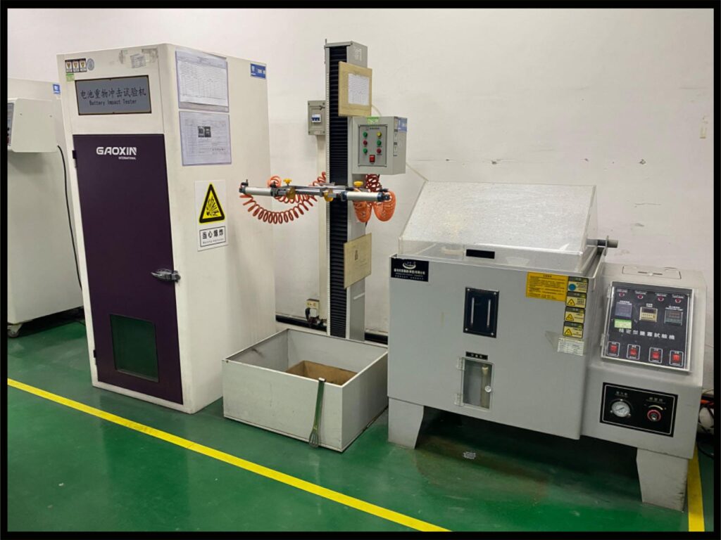
Include contact and thermal conditions
Dock contacts, wiring and connectors must suit the intended duty cycle and environment. Tell the design team about expected docking frequency, contamination, vibration and temperature conditions. Mechanical wear or poor engagement can affect the interface even when the battery itself meets its specification. Ask for the agreed inspection and maintenance approach. Charging tests should represent the installed robot and dock, including the surroundings and operating loads, rather than evaluating an isolated battery on an open bench only.
Keep versions and changes under control
Document the battery, charger, dock hardware and firmware versions used for validation. If the battery cell model, protection settings, connector or charging software changes, review which checks need repeating. Confirm how the supplier will notify you about proposed changes and how replacements will be identified in service. Jetray's robot solution category can support an initial battery discussion, but the complete docking design needs project-specific confirmation. A clear versioned baseline makes later maintenance and fleet updates easier to evaluate. A shared test log should identify intermittent contact events separately from battery faults, helping the teams investigate the correct subsystem.
Bring these points into the inquiry.
Use the checklist to organize a project discussion, then request the exact model specification, drawing and relevant evidence.
| Review point | Information to agree with the supplier |
|---|---|
| Measure the mission profile | Capture the load during start-up, acceleration, turns, payload handling and idle periods. |
| Coordinate control interfaces | Confirm voltage limits, BMS signals and the system response to protection events. |
| Test the charging workflow | Evaluate charging opportunity, connector wear, temperature monitoring and the return-to-service criteria. |
Sources & further reading
Prepared for the robotics & agv battery projects collection. General engineering guidance does not replace a model-specific datasheet or application validation. Source review: 4 November 2026.