The practical answer.
Calculate opportunity charging from net energy entering the battery during the actual stop, after the robot’s awake loads and applicable charging constraints. Charger nameplate power multiplied by parking time is not enough. Verify the measured battery-energy gain across repeated missions, including thermal conditions, charging taper and interrupted opportunities. A short stop can improve availability without making the overall duty cycle energy-neutral.
Define the energy boundary before calculating a charging window
Separate wall input, charger DC output, the robot's system supply and the battery terminals. Mixing those boundaries can count conversion losses twice or ignore an awake load entirely. State where each power value is measured and whether it includes accessories, computers and communications. The required result is energy entering the battery under the approved operating conditions, not energy delivered to some other node that happens to be near the charging connector.
TI's BQ25672 illustrates how a power-path architecture can allocate input power between a system and a battery. It is not a charger selection for the robots listed here. Delta-Q's IC Series describes optional CAN integration, but an optional bus does not establish a compatible message contract with a particular pack. Use these examples to formulate questions for the actual hardware suppliers, then obtain configuration-specific answers.
Work through a transparent hypothetical energy budget
Assume a hypothetical charging arrangement supplies 600W of DC power at the defined robot input while awake electronics consume 120W. The preliminary battery-side allowance before remaining downstream losses and constraints is 480W. Over a 20-minute stop, that corresponds to 160Wh. If an explicitly hypothetical effective charging fraction reduces that opportunity to 80%, the planning result becomes 128Wh. None of these figures is a Jetray rating or an observation from a robot fleet.
Keep the reduction assumption visible rather than disguising it as measured charger efficiency. It could represent time lost to alignment and validation, charge taper, permitted thermal derating or interrupted availability, but those causes should be measured separately in the actual project. If the real measurement boundary is already the battery terminals, avoid subtracting the awake system power again. A clear accounting boundary is more valuable than a precise-looking result built from inconsistent definitions.
| Quantity | Measurement boundary or context | Why it matters |
|---|---|---|
| Charger DC output | Defined point after charger conversion | Separate capability from wall-input power |
| Awake robot load | Same stop and operating state | Avoid counting system power as battery gain |
| Battery energy change | Approved pack terminals and method | Directly evaluate the useful charging result |
| Available charging time | Actual enabled period within the stop | Expose alignment and interruption losses |
| Repeated-cycle balance | Mission demand versus recovered energy | Identify a cumulative shift deficit |
Check the repeating mission, not only a single stop
Suppose a hypothetical mission consumes 150Wh and the following stop restores 128Wh. The planning deficit is 22Wh per cycle. Across eight identical cycles, it totals 176Wh before other changes. A larger battery might buffer the deficit, but that does not make the schedule indefinitely sustainable. The fleet plan needs to identify when and how the cumulative energy is restored, using validated charge permissions and the actual availability of the charging location.
Also model variability. Waiting for a dock, a robot that arrives later, a shortened break or an unusually demanding task can change the balance. Treat a missed charging opportunity as an operating scenario for the responsible fleet and control teams, not as permission to force a higher charge rate. Request evidence for both representative repeated operation and the approved response when the planned recovery window is not available.
Treat charge current and contact heating as distinct constraints
A power target does not by itself establish that the battery and installed connection can support the corresponding current. Ask for the approved charging envelope and the applicable contact, harness and connector conditions. A hypothetical 20A flowing through a hypothetical 0.01-ohm connection dissipates 4W according to I²R. That is a sensitivity example, not a permitted resistance, current or temperature rise for a docking interface.
Repeated stops can matter because the starting thermal condition may change through a shift. A test after a long cool-down is not automatically representative of the next opportunity charge. The responsible engineers should select measurement locations, pass criteria and environmental conditions for the installed assembly. Do not infer contact suitability from a battery capacity label, and do not bypass a temperature or connection interlock to meet a schedule assumption.

Produce an energy-gain acceptance record
Record the approved battery, charger, robot and interface revisions together with stop duration, relevant initial state, awake loads and measured energy at the chosen boundary. Capture interruptions and reasons for charge-current reduction where available. Compare multiple opportunities under defined conditions rather than reporting only the most favorable stop. The acceptance criterion should describe the required mission support, not a generic claim that fast charging works.
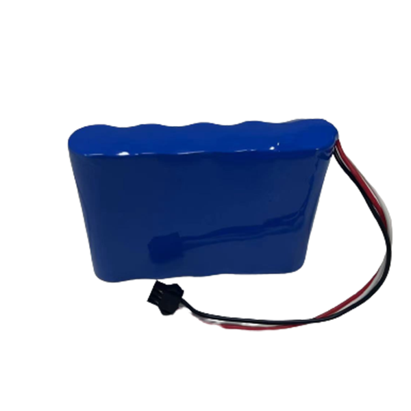
For Jetray, the 24V 26Ah and 36V 18.2Ah entries are robot application evaluations, while the 18.5V 5Ah pack is a published catalogue reference. None establishes the hypothetical charging power used above. Send the measured mission and stop-energy record with an inquiry and ask what the proposed assembly can document. Keep increased fleet availability, cell life, commercial warranty and infrastructure cost as separate questions; the simple net-energy equation does not answer all four.
Frequently asked questions
Is charger output power multiplied by stop time the battery gain?
Only under assumptions that must be stated and verified. An awake system, conversion stages, charge taper and unavailable time can reduce the gain. Measure at a defined boundary and avoid subtracting the same loss twice. A nameplate rating describes capability under specified conditions, not guaranteed energy at every opportunity.
Does more opportunity charging always mean a smaller battery is adequate?
No. The robot still has to meet its approved mission and contingency requirements when an expected opportunity is missed or restricted. A schedule model should be evaluated alongside electrical limits, operating variability and the equipment team's required reserve. This article supplies no universal battery-size rule.
Can a higher requested current fix a charging deficit?
Not without the actual battery, charger, connection and thermal limits supporting it. A deficit may be better addressed through scheduling, loads or infrastructure. The responsible teams must evaluate the options and verify the resulting operating plan. Catalogue related products do not authorize a higher charge rate.
Sources & further reading
- Texas Instruments BQ25672: NVDC power-path and battery supplement operation ↗
- Delta-Q IC Series: optional CAN and charger integration documentation ↗
- TI BQ76952 battery monitor and protector: separate charge/discharge protection ↗
- Jetray original product and application navigation ↗
Prepared from primary technical sources and original engineering analysis. All numerical scenarios are hypothetical planning examples, not Jetray measurements, customer cases or verified product ratings. Catalogue links are evaluation references; exact application suitability and approval require documented project validation.
Prepared for the robotics & agv battery projects collection. General engineering guidance does not replace a model-specific datasheet or application validation. Source review: 5 November 2026.