The practical answer.
Treat regenerative current as a charging event produced by the drive, not as a small correction to the robot’s average energy budget. The battery must be permitted to accept that current in its present state, and the drive must respond appropriately when acceptance is reduced or withdrawn. Agree current direction, limits, validity, timing and fault behavior across the battery, drive and robot controls. A pack’s discharge rating alone does not establish regenerative compatibility.
Draw every route for current into the battery
Start with a block diagram showing the cells, protection path, charger port, traction DC bus and drive controllers. Mark the current sign at each measurement location. Some teams use positive current for charging while others use it for load current. An unexplained sign difference can turn a protective limit into an apparently generous discharge allowance. Make the sign convention a required field in both the battery interface document and the robot telemetry definition.
Identify whether braking or deceleration can return energy through the traction terminals. TI's motor-driver discussion explains how a decelerating motor can act as a generator and raise the supply voltage through reverse current. This supports examining the direction of power flow; it does not establish the behavior of every controller. Ask the actual drive supplier which modes regenerate, which current is measured, and how the drive responds if the DC bus cannot absorb the returned energy.
Define a charge-acceptance envelope rather than a single current
Request the permitted charge-current envelope for the proposed assembly, including the conditions under which it changes. Battery state, temperature, cell-voltage margin and the actual protection implementation can all be relevant to the review. The supplier must identify the applicable dependencies and values. A nominal continuous discharge rating or a cell-level number is not sufficient evidence for a reverse-current pulse applied through the assembled pack, harness and protection path.
Give the drive team both the normal allowance and the unavailable state. A software interface should distinguish a known zero allowance from a missing or stale limit. Decide which values require supervisory action and which hardware mechanisms remain independent of communications. These are robot-system decisions; they cannot be delegated to an unspecified battery catalogue entry. Do not assume a full battery can accept every pulse that a partly discharged sample accepted during an early bench demonstration.
| Interface item | Question to resolve | Evidence |
|---|---|---|
| Current direction | Which sign and measurement location denote charging? | Shared schematic and trace legend |
| Charge allowance | What conditions change permitted current? | Model-specific envelope and validity rules |
| Protection path | What happens to reverse current in each FET state? | Supplier circuit explanation and applicable tests |
| Drive response | How is reduced or unavailable acceptance handled? | Versioned controller specification |
| Timing | Can signals and control respond within required bounds? | Synchronized system evidence |
Review the protection topology before assuming a current path
A common connector does not reveal how charging and discharging are controlled internally. TI's BQ76952 reference manual distinguishes series and separate charge/discharge FET arrangements and discusses body-diode behavior. The useful lesson is that an off switch in one control direction is not a complete description of every possible current path. The supplier should explain the actual circuit topology and its documented reverse-current behavior without exposing proprietary details unnecessarily.
Do not infer that a body diode provides an acceptable continuous regeneration path. Request the actual permitted operating states and thermal evidence for the assembly. A robotics team should not bypass a protection switch, force a recovery state or change undocumented registers to make a test pass. If a controller assumes a permanently receptive source while the battery can disconnect, the interface needs engineering review. Changing the capacity label does not resolve that architectural mismatch.
Separate returned energy from the short bus-voltage event
A hypothetical robot returns 400W for 0.5 seconds during one deceleration. The energy is 200J, or about 0.056Wh. That appears small compared with a battery energy rating, but it says little about the peak bus voltage when the charging path is unavailable. This arithmetic is a planning example only, not a braking test, an energy-recovery claim or a rating for any linked Jetray battery.
For another hypothetical calculation, a 0.002F bus capacitor rising from 48V to 54V stores an additional 0.5 × 0.002 × (54² − 48²), equal to 0.612J. This does not define a recommended capacitance or voltage limit. It demonstrates why a small returned-energy event cannot automatically be assigned to an arbitrary capacitor. The responsible designer must evaluate the real bus, controls and any approved energy-handling hardware, including transient and repetitive thermal constraints.
Agree the timing contract between the battery and the drive
Create an interface table for allowable charge current, relevant voltage margin, temperature state, protective status and data validity, where those signals exist. State units, resolution, update interval and timeout behavior. Include the timing relationship between a battery warning, a commanded reduction and the possibility of a hardware protective action. If the required timing cannot be supported by communications alone, the responsible control team must address that limitation in the architecture.
Keep the drive's battery-current limit separate from its motor-phase settings. They need not represent the same quantity or duration. Ask which setting limits energy returned to the DC bus and how it interacts with torque commands, vehicle motion and a lost battery message. A high motor-current headline is not a substitute for that answer. The goal is a coordinated contract that each supplier can evaluate, not a collection of independently attractive maximum ratings.
Construct an evaluation matrix around changing acceptance
An engineering test matrix should include more than repeated deceleration at a comfortable battery state. Have the responsible teams choose representative and restrictive conditions within approved limits, then identify what evidence each test must produce. Relevant questions may include whether current follows a reduced allowance, whether the host recognizes stale data, and what the drive does when the intended charging path is unavailable. The exact scenarios and pass criteria require a system risk assessment and qualified supervision.
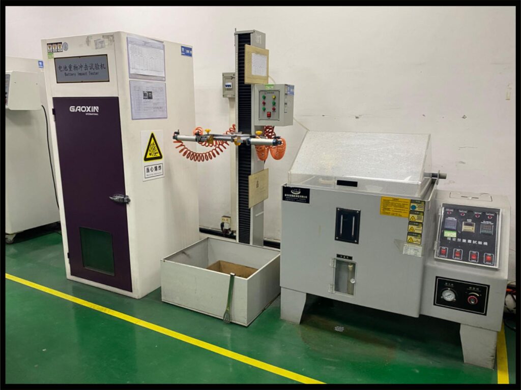
Use synchronized measurements where timing matters. Pack current, DC-bus voltage, drive state and battery status should be interpretable on one timebase. Record sensor location, current sign and sample resolution so a short event is not averaged away or mistaken for a communication glitch. Perform validation in a controlled engineering environment using approved procedures. This article does not direct operators to provoke a protection trip or test braking behavior on a working public route.
Investigate event sequences before assigning a battery fault
An overvoltage log and a battery-disconnect log do not by themselves reveal which event happened first. The battery may have withdrawn acceptance before the drive event, or a drive transient may have preceded a protective response. Compare timestamps, measurement limitations and command history. Where logs do not have enough resolution to establish causality, record that uncertainty and plan an appropriate investigation instead of turning the most visible error code into a conclusion.
Also separate a controller's response from the complete robot outcome. A drive that reduces regeneration may affect other system behavior that must be assessed by the robot manufacturer. Restoring electrical operation does not automatically authorize a return to motion. Keep the approved recovery conditions in the robot state machine and service instructions. A supplier can provide component evidence, but only the responsible system teams can decide whether the integrated behavior meets the robot's requirements.
Keep catalogue candidates outside an unverified compatibility claim
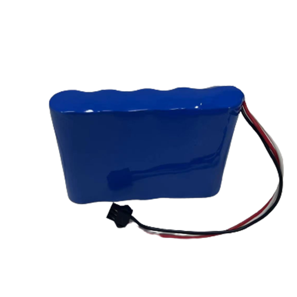
The 18.5V 5Ah published reference, 24V 26Ah robot evaluation and 36V 18.2Ah robot evaluation represent different starting discussions. The catalogue does not establish a common BMS, regenerative-current allowance or communication protocol across them. Request the current specification, protection-path description and model-specific data for the candidate being proposed. A family photograph on this page is contextual material, not proof that a pictured assembly has passed an AGV regeneration test.
For an inquiry, send the drive model, DC-bus operating window, measured reverse-current trace and proposed interface contract. State whether the measurement describes a single event or repeated duty and identify the approved test conditions. Ask Jetray which parts of the requirement can be documented for the proposed pack and which need development or additional validation. Resolve those questions before treating a pack as a platform standard or using one successful low-load result to release a fleet.
Frequently asked questions
Can a battery with a large discharge rating always absorb braking current?
No. Discharge and charge permissions are different. Regenerative current must pass through the actual assembled charging path under the present battery conditions. Request its magnitude, duration, repetition and operating restrictions separately. A discharge specification alone does not establish reverse-current compatibility.
Is adding bus capacitance enough to solve a regeneration problem?
There is no universal answer. Capacitance stores a finite amount of energy over a permitted voltage rise, while the drive and battery can create longer or repeated events. A qualified system designer must evaluate the actual event and approved energy-handling strategy. The hypothetical calculation above is not a component-selection instruction.
Does the presence of a BMS make the robot's braking function safe?
A BMS provides specified battery functions; it does not by itself validate the integrated robot or its motion behavior. The drive, controls, mechanical system and battery must be assessed together. No Jetray catalogue reference on this page establishes a certified robot braking function or universal AGV compatibility.
Sources & further reading
- TI SSZT878: regenerative motor current and supply-voltage overshoot ↗
- TI BQ76952 Technical Reference Manual, section 5.2.3 FET configuration and control ↗
- TI BQ76952 battery monitor and protector: separate charge/discharge protection ↗
- Jetray original product and application navigation ↗
Prepared from primary technical sources and original engineering analysis. All numerical scenarios are hypothetical planning examples, not Jetray measurements, customer cases or verified product ratings. Catalogue links are evaluation references; exact application suitability and approval require documented project validation.
Prepared for the robotics & agv battery projects collection. General engineering guidance does not replace a model-specific datasheet or application validation. Source review: 5 November 2026.